
In automotive assembly, reducing worker fatigue and improving assembly quality are key goals. Assistive lifting devices play a crucial role in achieving these by enabling the smooth handling and precise positioning of heavy components. As labor costs rise and the demand for consistent installation grows, the automotive industry increasingly relies on assistive manipulators with higher levels of automation.
Overview of Assistive Manipulator Applications
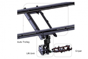
Assistive manipulators are evolving from manual assistance to more automated systems. A typical system consists of three main components: the rail and trolley, the lift unit, and the gripper (Figure 1). The lift unit can be further categorized into vertical lift or four-link systems.
In automotive assembly, different lines require specialized assistive manipulators. For instance, the interior line often uses door removal manipulators, sunroof handling devices, and dashboard installation manipulators. The chassis line may require manipulators for front-end modules, fuel tanks, batteries, and exhaust systems. On the rear interior line, seat and tire installation are common use cases.
Automated Assistive Manipulators
There are two common modes for automated assistive manipulators: passive and active following. Passive following attaches the manipulator to the vehicle, moving in sync with it. Active following, however, uses PLC control to adjust the speed of the manipulator’s drive motor, ensuring it moves at the same pace as the vehicle (Figure 2). Due to its simplicity, passive following is not covered here. Instead, we’ll focus on the active following method.
Active Following Drive System
For the active following system, the manipulator’s drive motor (M2) controls movement. In this case, we use an SEW gear motor with a 4-pole configuration and a rated speed of 1440 rpm, driven by a frequency of 50Hz. The drive wheel has a diameter of 0.2m, leading to a calculated direct drive speed of 904.32m/min. However, the manipulator’s operating speed needs to be significantly lower, with typical forward/reverse speeds not exceeding 22 m/min. To achieve this, the system uses a reduction ratio of 41.1:1.
For production lines with a takt time of 30 jobs per hour and a station distance of 6m, the required line speed is 3 m/min. The manipulator�s speed is synchronized with this line speed during active following, ranging from 3 to 22 m/min. The motor’s output speed is then adjusted through the gearbox, and the drive system ensures smooth, consistent operation throughout the process.
Frequency Control
To maintain proper torque and speed control, the frequency inverter adjusts the motor speed. For example, using a Siemens G120 inverter, the frequency is set between 10Hz and 50Hz, corresponding to preset values that control the speed range of the manipulator. By analyzing these operational factors, we can achieve synchronized, smooth movement of the manipulator along the assembly line.
Active Following Control Models
We�ve developed two main models for active following:
- Wait-and-Synchronize: The manipulator waits in a standby position until the vehicle arrives. Once the vehicle is in place, the manipulator synchronizes its movement to match the vehicle’s speed (Figure 3). This reduces operator fatigue and improves installation efficiency.
- Chase-and-Synchronize: If the vehicle has moved ahead, the manipulator must first catch up before synchronizing with the vehicle (Figure 4). This method is useful in situations where previous processes have delayed the vehicle’s progress.
These models allow flexibility in adapting to different production line conditions. Both modes are critical for meeting the demands of real-world production environments.
By integrating PLC programming, we provide solutions that ensure smooth, efficient operation of assistive manipulators in automotive assembly lines. These methods serve as valuable references for companies aiming to improve the safety, speed, and precision of their handling systems.